FEBEX module Hardware Configuration & Test Diagnostics
All FEBEX modules must first be configured correctly by setting the appropriate switches.
FEBEX modules MUST be inserted into the crate starting from the left hand end. There MUST not be any empty slots between modules.
The software currently supports up to 10 modules in a crate; 4 crates and 1 PEXOR module. Hence a total of 40 modules which is 640 ADC channels.
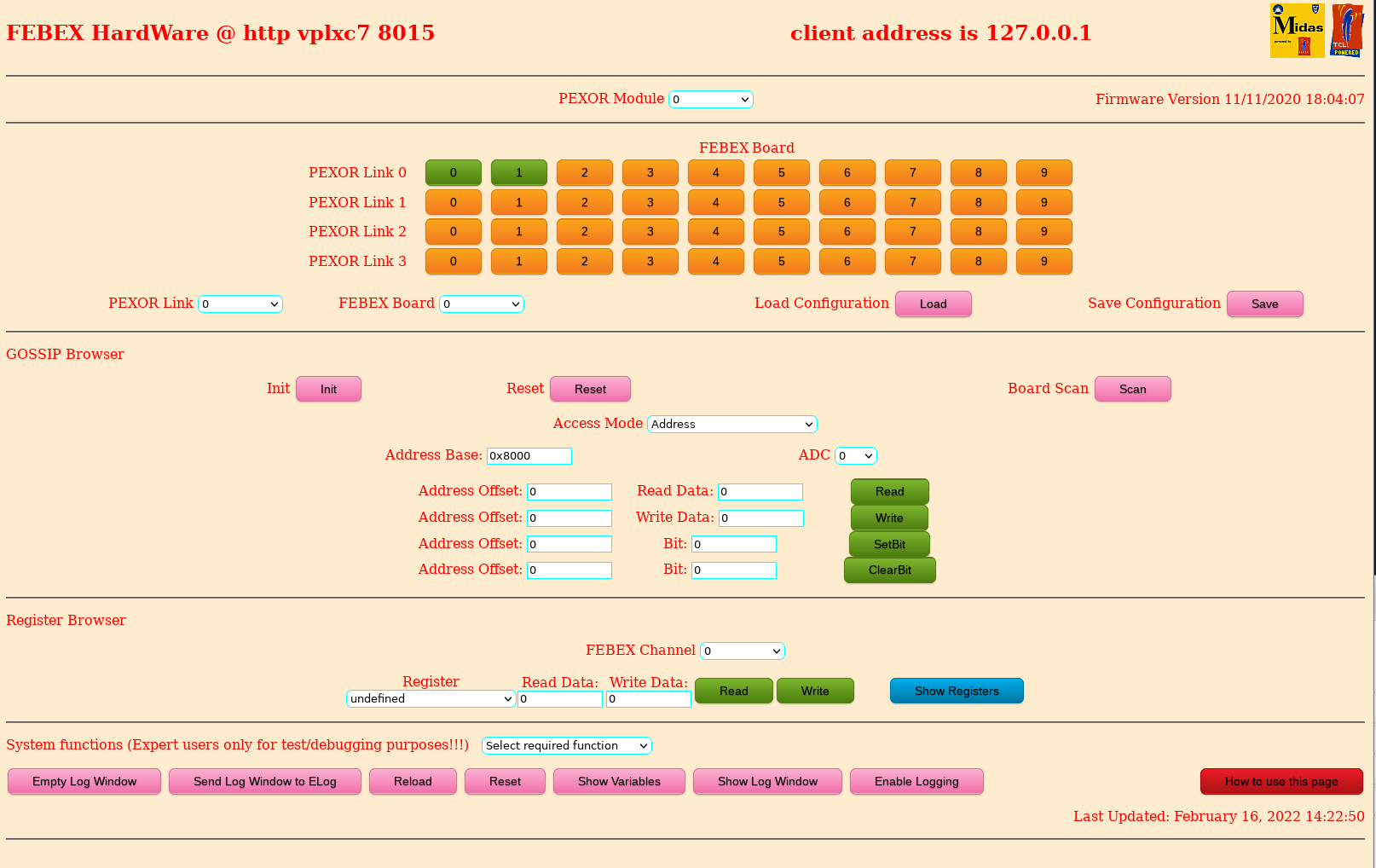
PEXOR Module:   Selects the PEXOR card to be used. Module n => /dev/pexor/n. Currently only 1 module is in use.

To select the FEBEX boards on each PEXOR Link click on the button. Green is installed and orange is empty.
Click to change state. Remember the rules - no spaces between modules.

PEXOR Link:     Selects the PEXOR SFP link to be used. Each PEXOR Module supports 4 links.

FEBEX Board:    Each PEXOR Link can link to a number of client modules (FEE). This selects the 16 channel ADC board.

The hardware layout is automatically saved when changed by selecting a FEBEX board.
The boards for a Link must be consecutive.
This configuration can be saved and restored at any time by the Load Configuration and Save Configuration buttons.

A number of inbuilt functions are available which act on the current module, link and client.

All functions will connect to the selected module if it is not already connected. Uses mbspex_open

Reset:          reset dma and sfp engines. Uses mbspex_reset

Init:           initialise chain for the current link (sfp) for n boards (defined by the Board parameter).
                Uses mbspex_slave_init and mbspex_reset.

Scan:           Goes through all PEXOR links & FEBEX boards and executes the Reset & Init commands
                + reads the firmware version information.
                Produces a summary of the hardware responses.
                This is a very usefull way to check the hardware configuration in use.
                DO NOT USE when the Data Acquisition is in the GO state.

Access Mode:    This diagnostic supports 2 ways of defining the address to be accessed
                on the FEE selected by the Slave ID.
             Address    You supply the Address Base and Address Offset which together combine
                        to give the 24 bit address on the FEE
             ADC        You supply the ADC channel number which together with the Address Offset
                        combines to give the 24 bit address on the FEE

Address  Base:   Only used when the Access Mode is Address. This defines the Base address of the data area to be accessed.

ADC:             Only used when the Access Mode is ADC:  The Base address is (ADC Ch number * 0x008000) + 0x008000

Address Offset:  The data register address to be accessed is  Address Base + Address Offset (a byte address).
             Note that there are 4 "Address Offset" inputs.
             These are used for the related operation Read, Write, SetBit and ClearBit.

Write Data:        Defines the data to be used by a write access to the current data register address. Currently not used.

Read:              Execute a read access to the current data register address.
                   The data returned is shown in "Read Data". Uses mbspex_slave_rd

Write:             Execute a write access to the current data register address with the supplied data.
                   Uses mbspex_slave_wr

Setbit:            sets the bit supplied in the data register defined by Address Offset.
                   Uses mbspex_slave_rd & mbspex_slave_wr

Clear Bit:         Clears the bit supplied in the data register defined by Address Offset.
                   Uses mbspex_slave_rd & mbspex_slave_wr

Note:   The "Show Variables" button shows all the important internal variables used by the software.

The gosipcmd program (goc)  is directly equivalent to these functions.

   Reset is  equivalent to the command  goc -z -n **
   Init  is  equivalent to the command  goc -i [link] [client]
   Read  is  equivalent to the command  goc -r [link] [client] [address]
   Write is  equivalent to the command  goc -w [link] [client] [address] [data]

   SetBit    is  equivalent to the command  goc -s
   ClearBit  is  equivalent to the command  goc -u

Register Browser:  For the selected Link, Board and Channel (where relevant)
                   you can read and write any of the defined firmware registers.

Register:      A menu of all registers known to the software
Read Data:     Contains the data returned by the most recent  Read operation.
Write Data:    Enter the data [decimal or hexadecimal (0x****)] to be used by the Write operation.
Read & Write:  Perform a single register access

Show Registers Starts a new tab (or opens an existing tab) to read and display ALL the registers
          for the current Link & Board.

Update Firmware Starts a new tab (or opens an existing tab) to update the firmware
          from a disc file for the current Link & Board.
V Pucknell; STFC; Daresbury Lab updated 10 March 2022